A short story about metamorphosis from SWL DX’er to a HAM Radio Amateur.

After I got bitten by the SDR Bug back in -12 I updated and upgraded my SDR equipment every year. Normally this meant that I bought and built new SDR receivers, computers, antennas etc and upgraded my SDR system from one single laptop computer and one RTL-SDR donge and one wire antenna to five Raspberry Pi’s, two NUC PC’s, 6TB external drive and 12 SDR devices and 15 antennas from long wires to active loops, 10 meter long vertical whip and MiniWhip active ‘can’, not to mention all other ADS-B, AIS, RTL_433 and so on.
Late 2020 I started my training to be licenced HAM, a Radio Amateur and got my license January 2021. It was time to re-born and re-think everything I have done before.
As told before in this blog of mine, my system is located some 250km’s away from where I live. I have no space for all the antennas here in city flat, nor are able to install anything bigger than a car whip to my balcony. The SDR equipment I have built to my remote site was already working great and as I later found out operating HAM radio remotely is not that hard either. The Icom IC-7300 series HAM transmitter is more than capable device for remote operation, so I could build fully remote operated HAM station!
The Shack
The perhaps most annoying thing what comes to a modern HAM radio is that they are noisy, I mean really noisy! The power supply needs to be able to power the IC-7300 with whopping 25A, abt 350Watts of power – this creates a lot of heat that needs to be push out from the PSU. Also the IC-7300 has a huge fan that is not that silent either. Also, the radio keeps noise when transimitting, relays are clicking like maniac especially during tuning phase.
It was clear that I need to move my system to another place. I have built my SDR based system next to bedrooms, upstairs vestibule to a small shelf high up in the wall next to ceiling. Place really not suitable for heavy noisy thingies that are on 24/7 and have bright lights, big screen, this and that.
The first, initial idea was to move the equipment out of the house, to balcony into some kind of cabinet. Keep everything well isolated from the elements of nature and also help with the cabling, 15 antennas requires a lot of cable!
Then an idea was to buid a real shack out, next to the actual antenna mast and remove everything from the house. This would also help with the EMI that was present in the house.
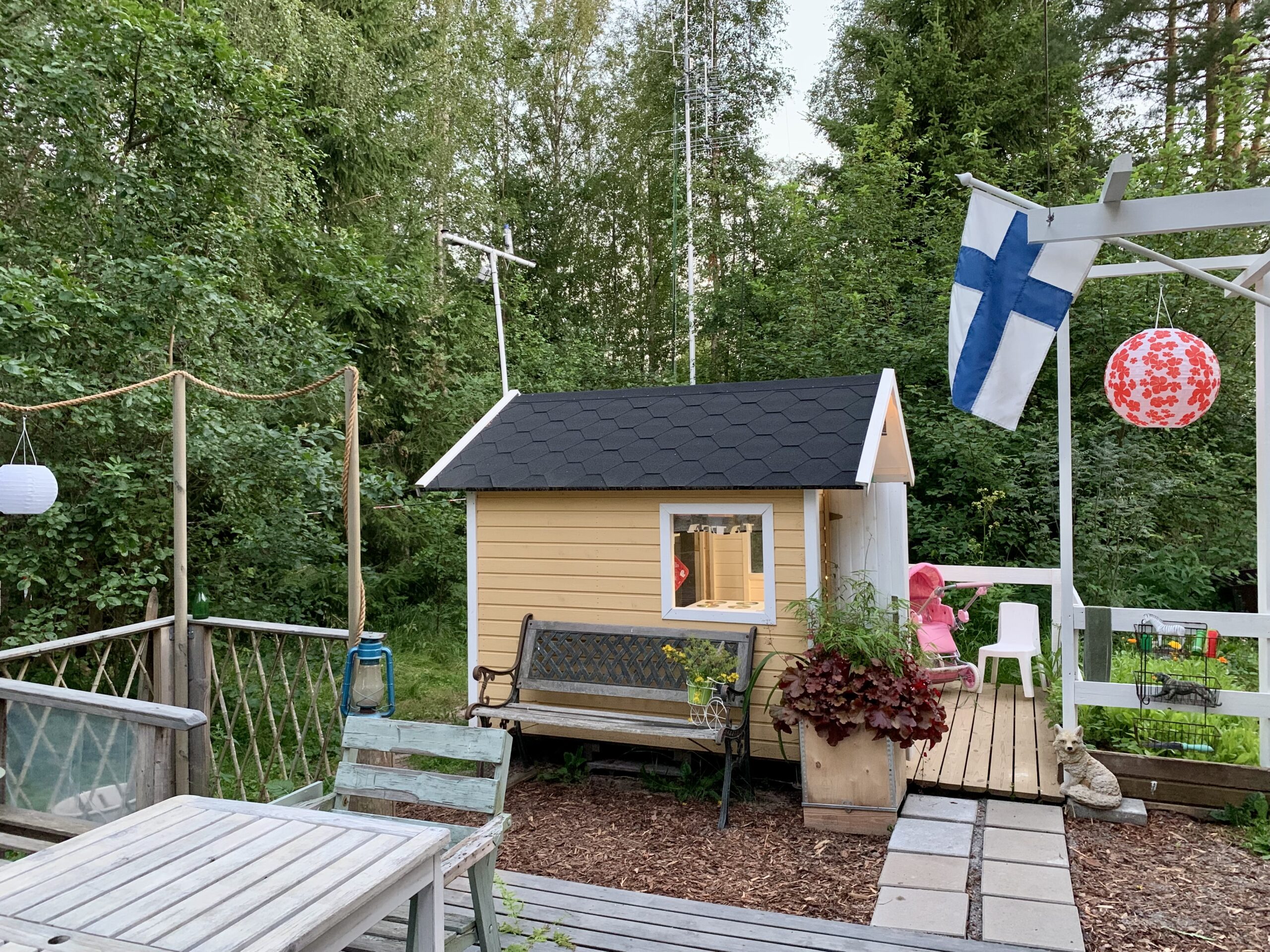
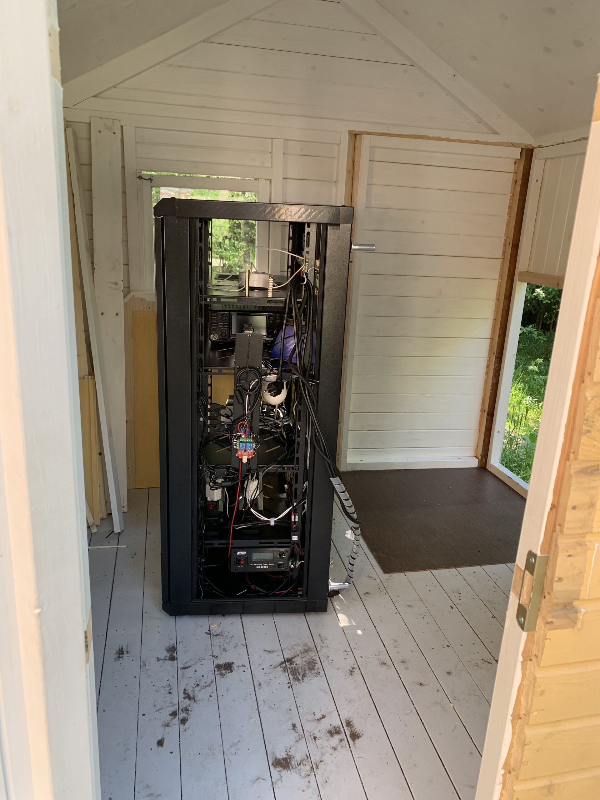
Next iteration was to actually get a playhouse and install all the radio stuff there, into some cabinet and mask them to be just a some kind of furniture. This was agreed to be the final solution.
So what actually was done and how?
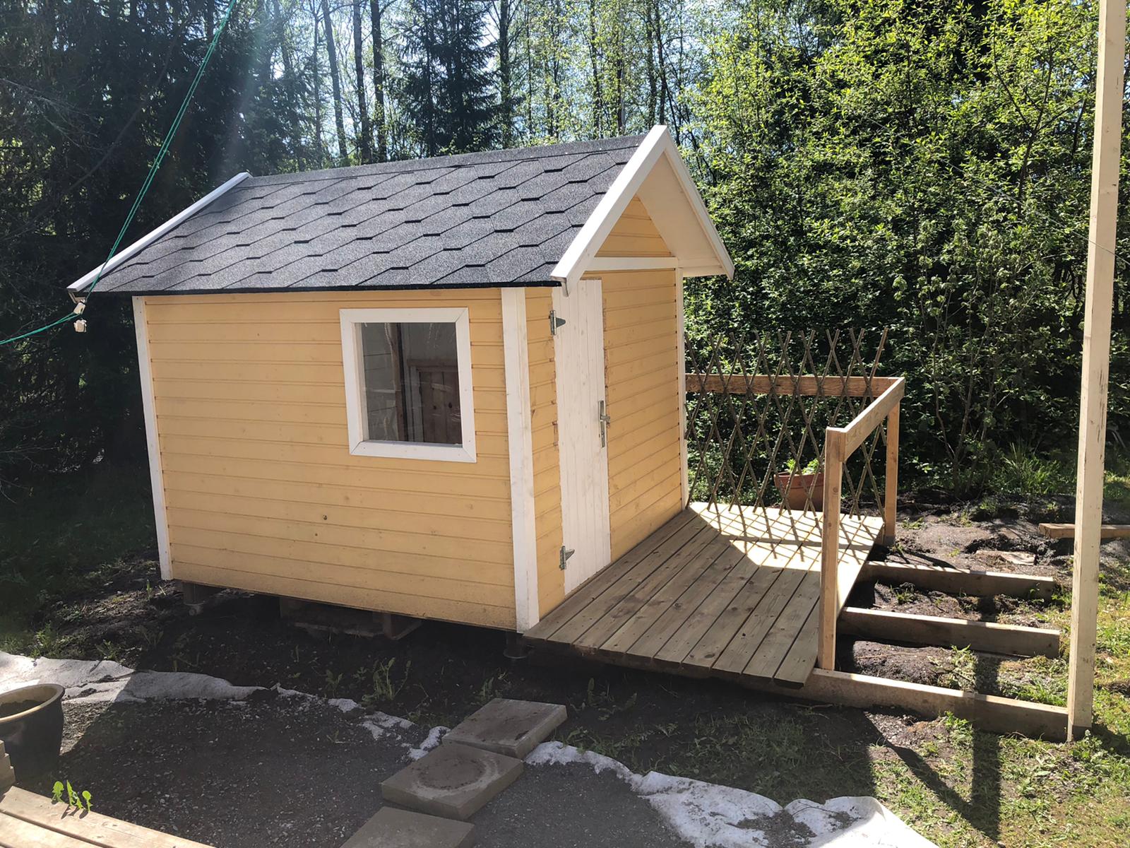
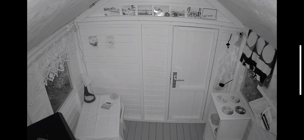
First came the playhouse. Luckily for us, a family of acquaintances were at the same time trying get rid of a playhouse, perfect! The cabin was awesome, only some minor adjustments were necessary to get room for the “fireplace”.
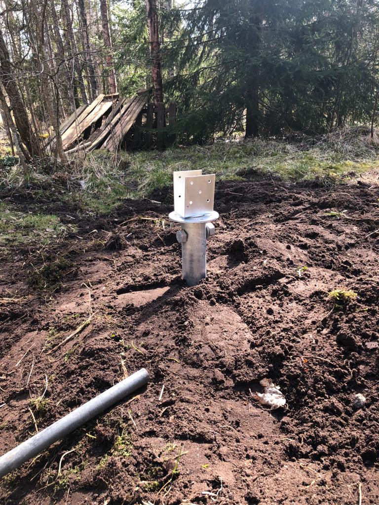
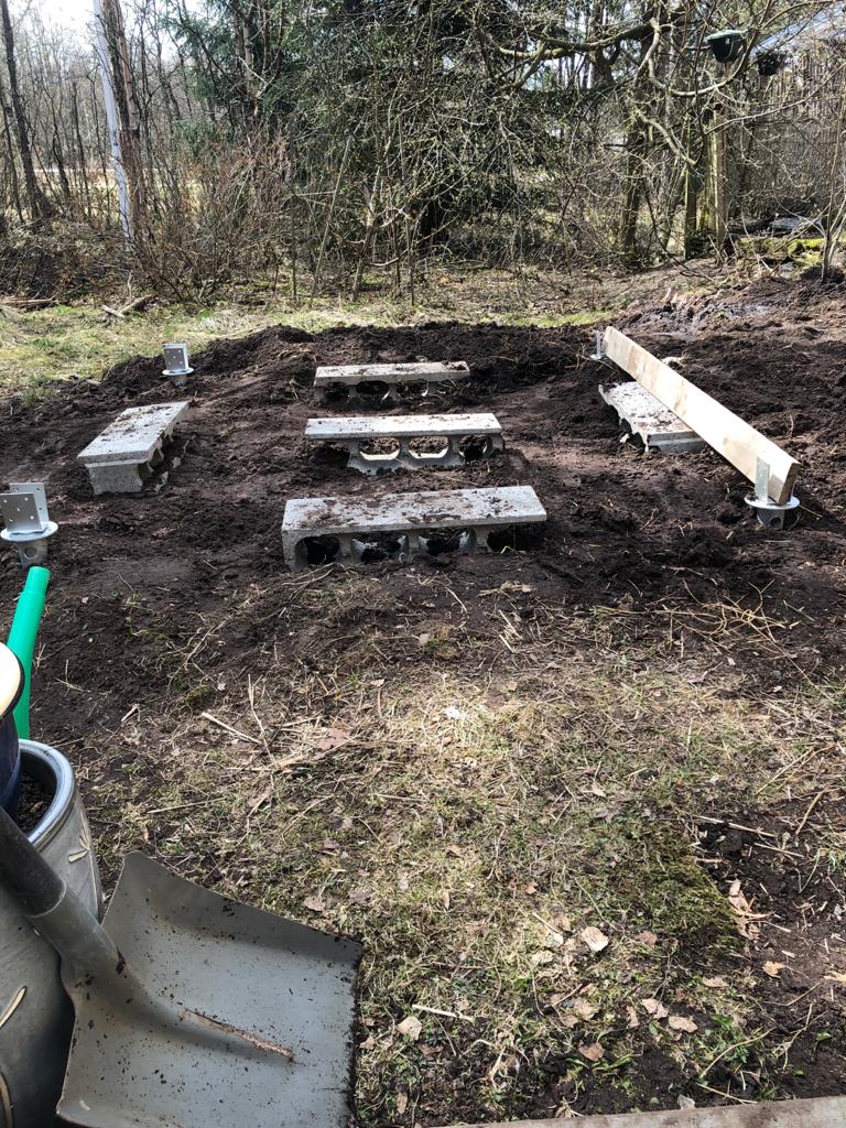
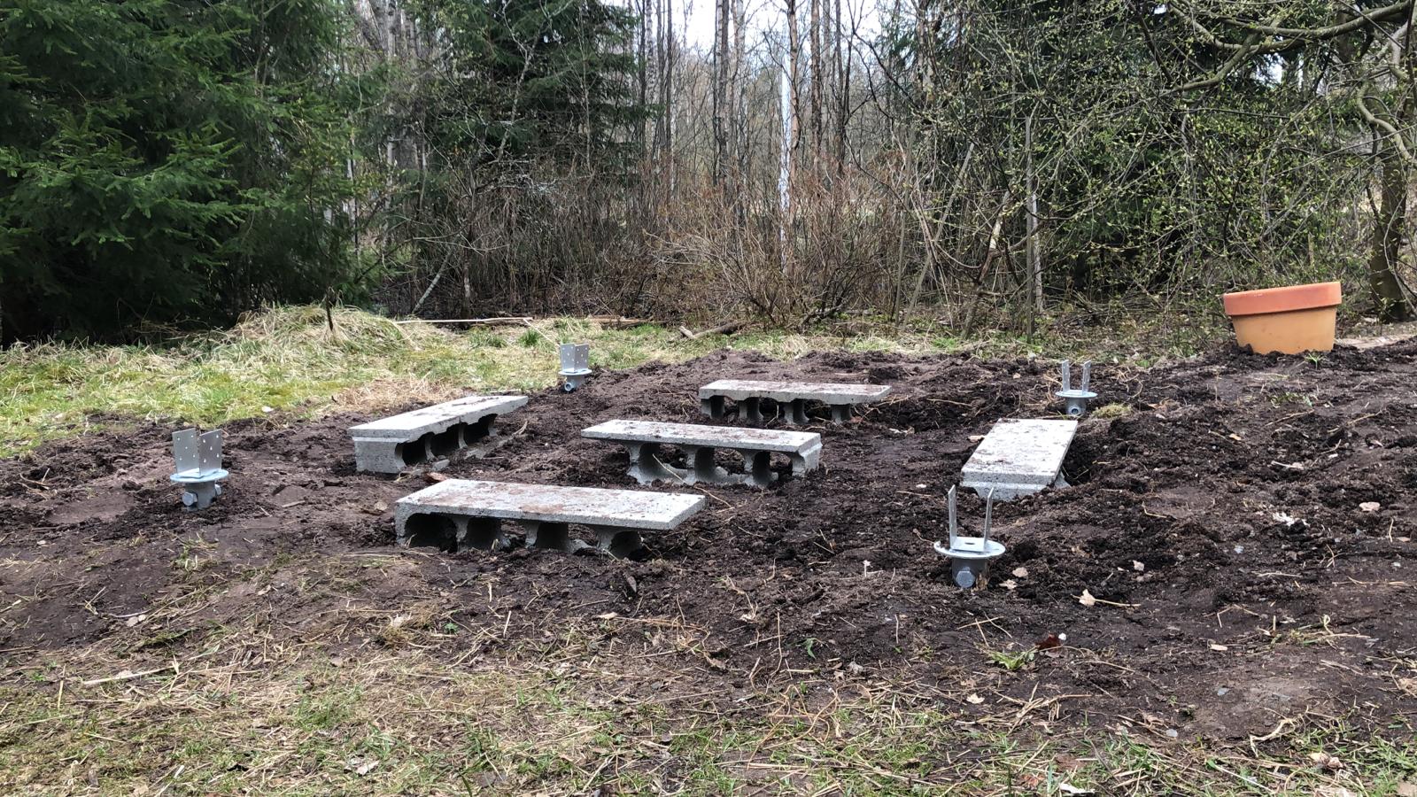
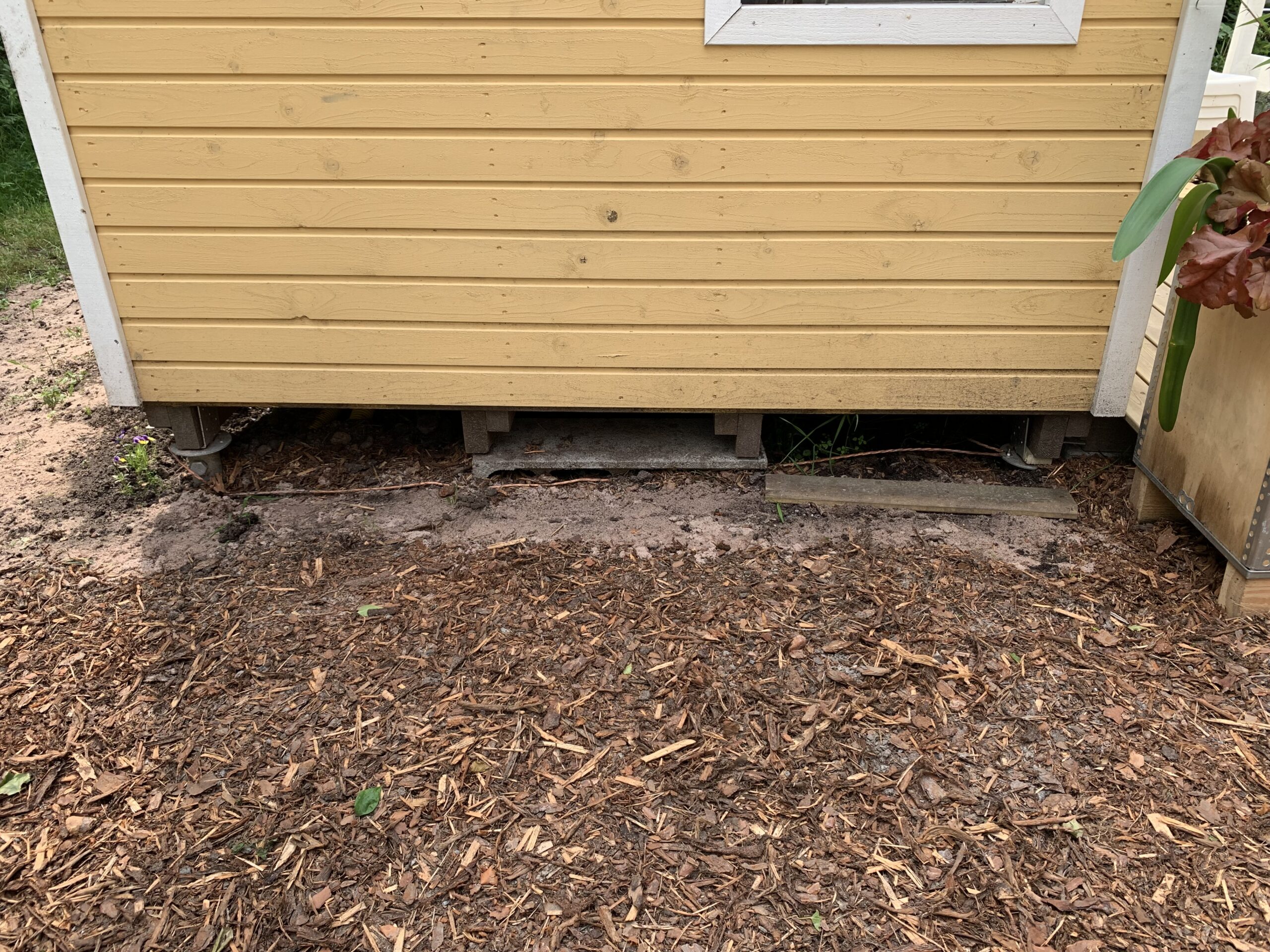
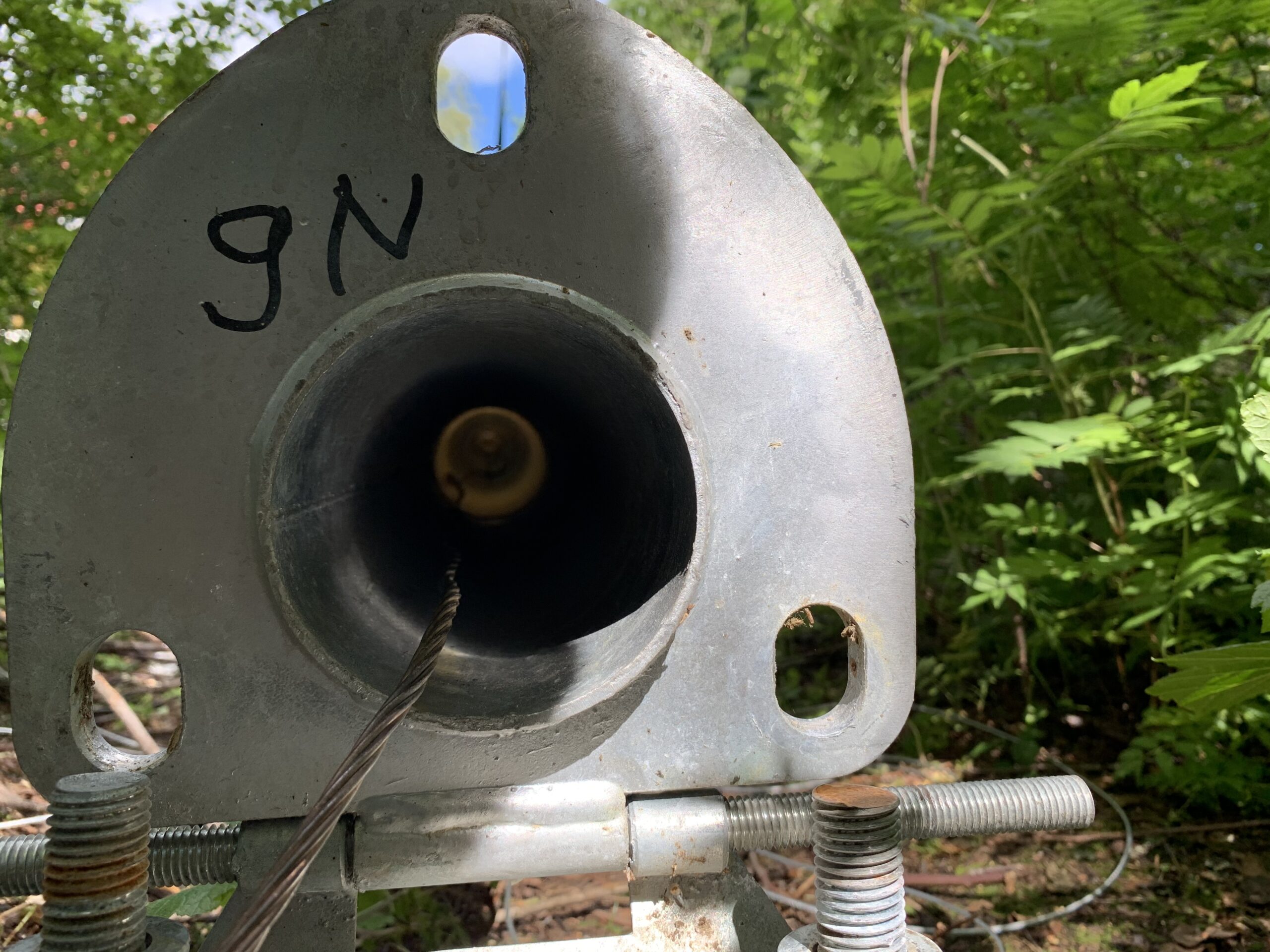
As it was clear that everything needs to be grounded well, we decided to mount the cabin using steel poles. These steel poles would go down 1,6 meters into the soil so they are perfect grounding points for the system. Also we decided to have a small patio and garden for my nephews and nieces to play with.
Second phase, power, internet and groundings. There were few absolute rules that needed to be followed what comes to the safety of the system, users and especially kids playing in the playhouse while radios are in use and powered on. No mains sockets or other hight voltage devices can be touched nor any part that may come hot can be be touchable by some “small hands”. In the design this was taken very seriously and everything was planned and built so that the cabin is as safe as it would be in the normal use as an pure playhouse.
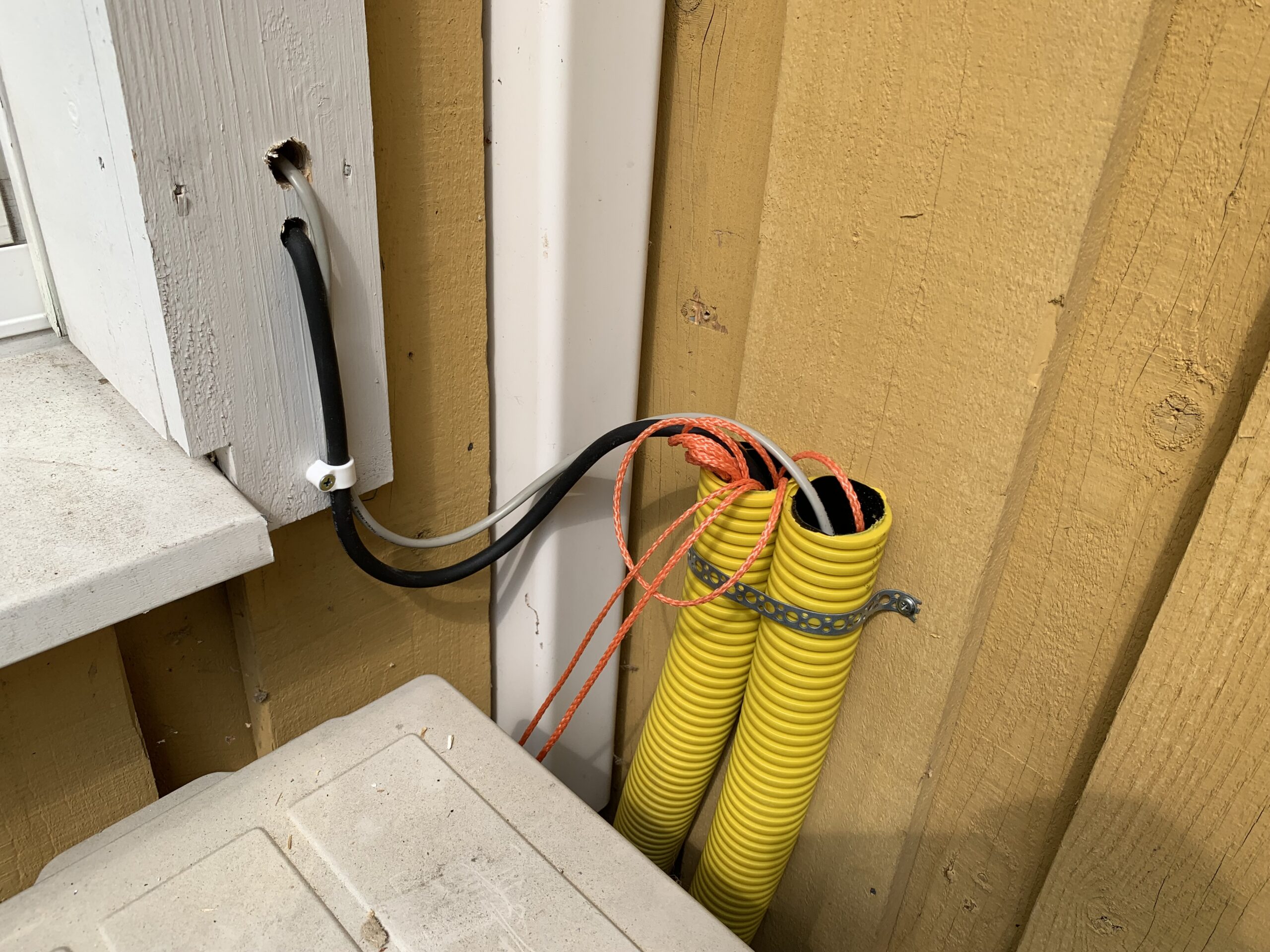
The mains comes to the cabin via special 550VA isolator transformer, RF-filtered and isolated from the house mains. This prevents any EMI travelling from the house via power line and also isolates the cabin from the main power grid grounding. At the cabin side, everything is grounded via the cabin poles with sturdy copper line.
Internet connection is provided both via ethernet cable and via WiFi connection. The ethernet cable has galvanic isolators at the both ends of the cable to prevent any DC current to travel via it from the house to the cabin or vice versa due to potential difference between the house and the cabin. This also helps to prevent any RF interference to cause any harm with the ethernet network installed while Icom is transmitting.
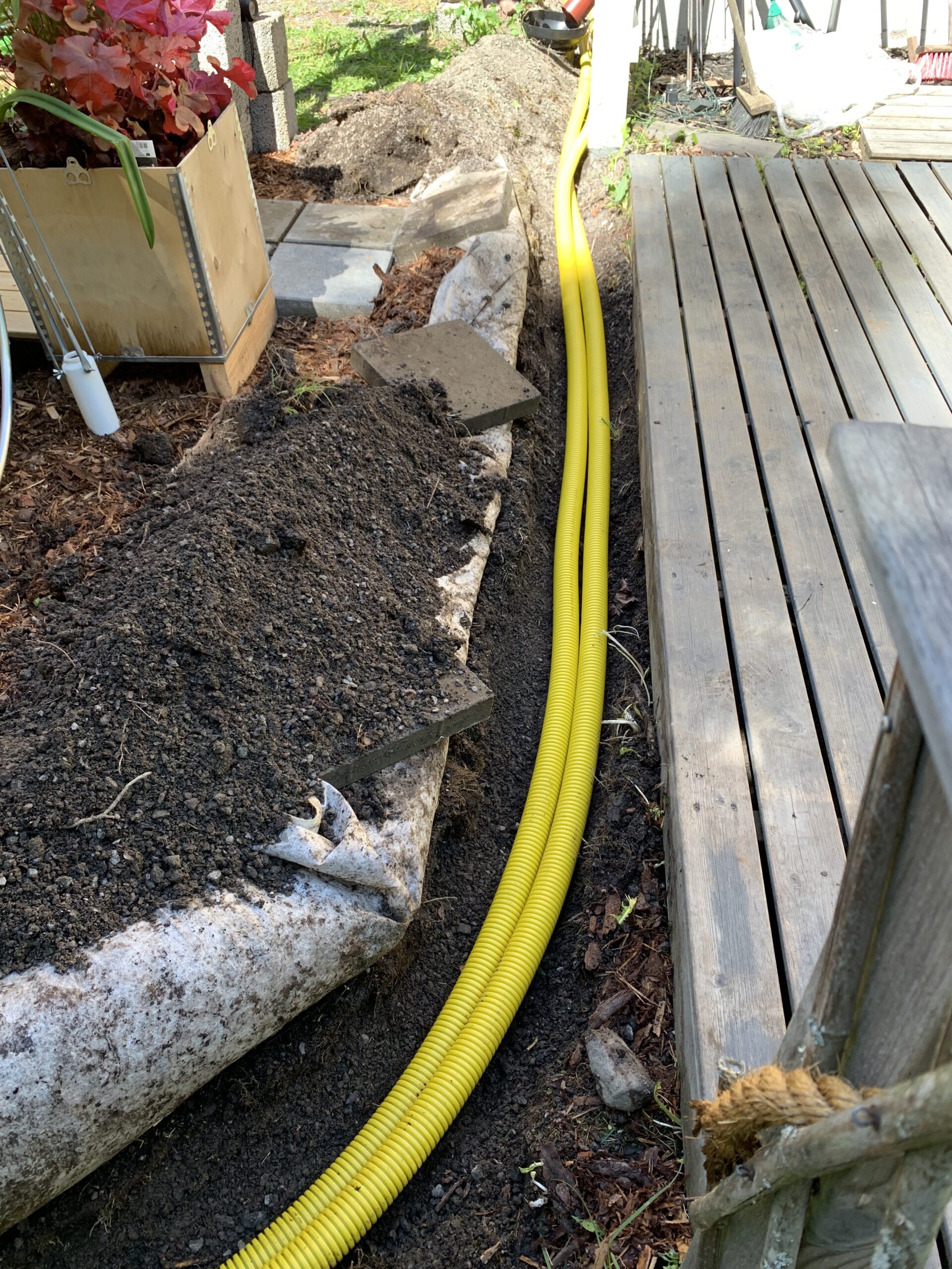
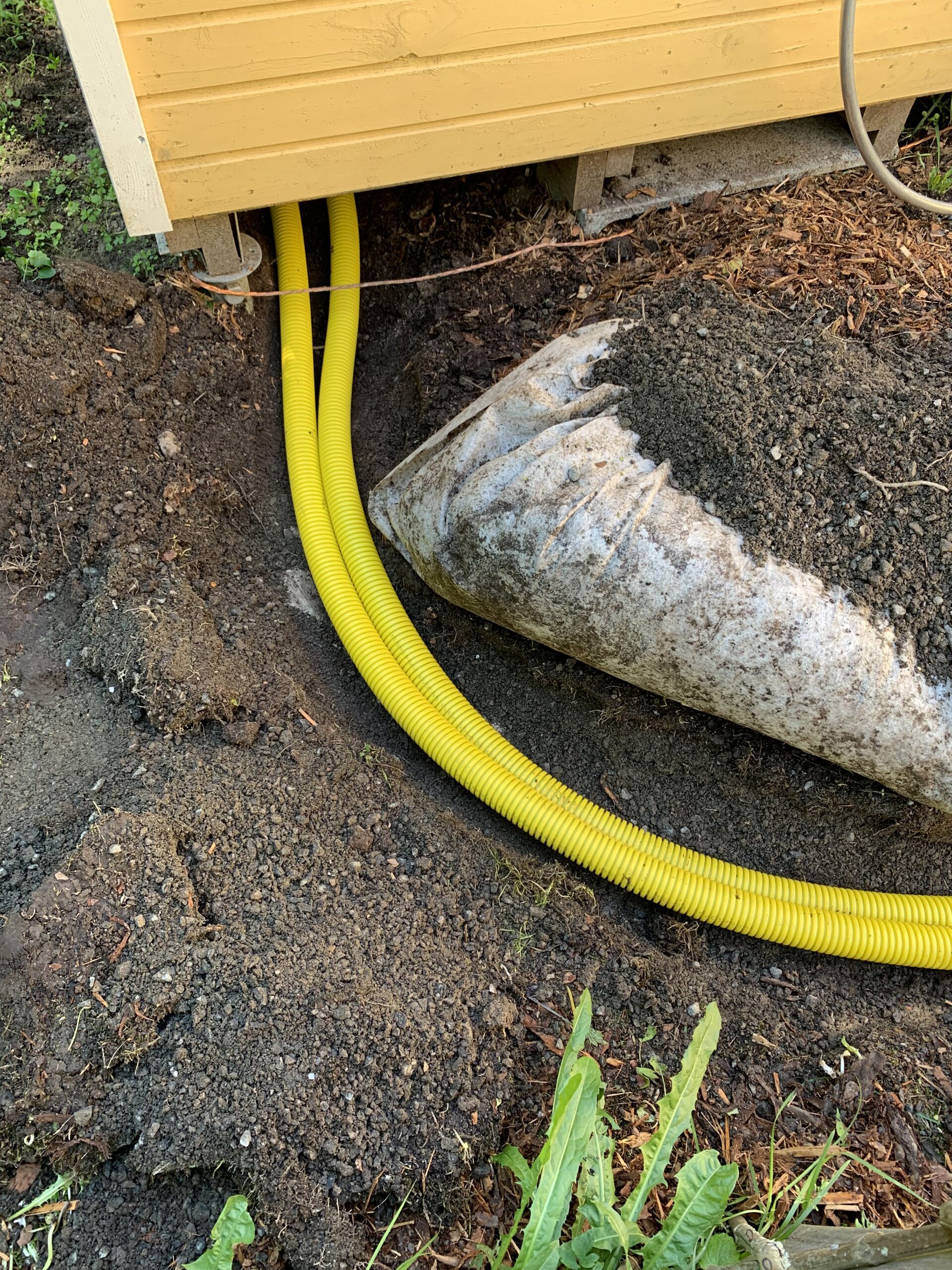
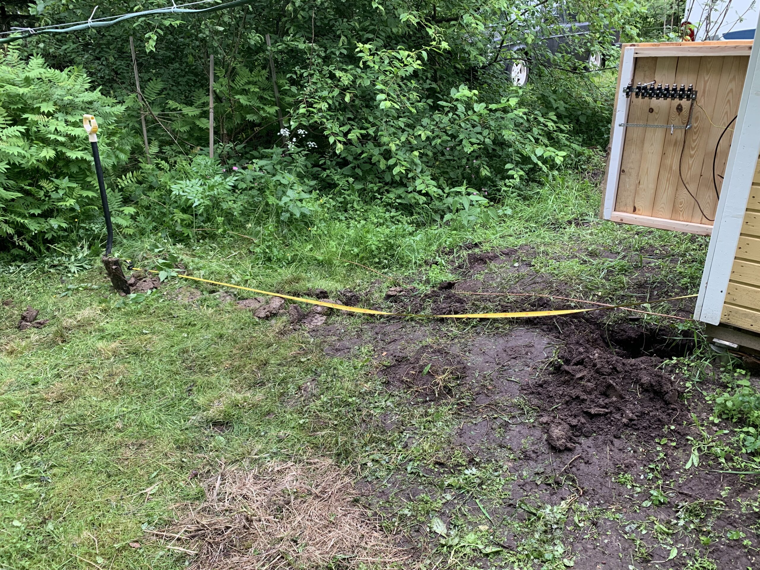
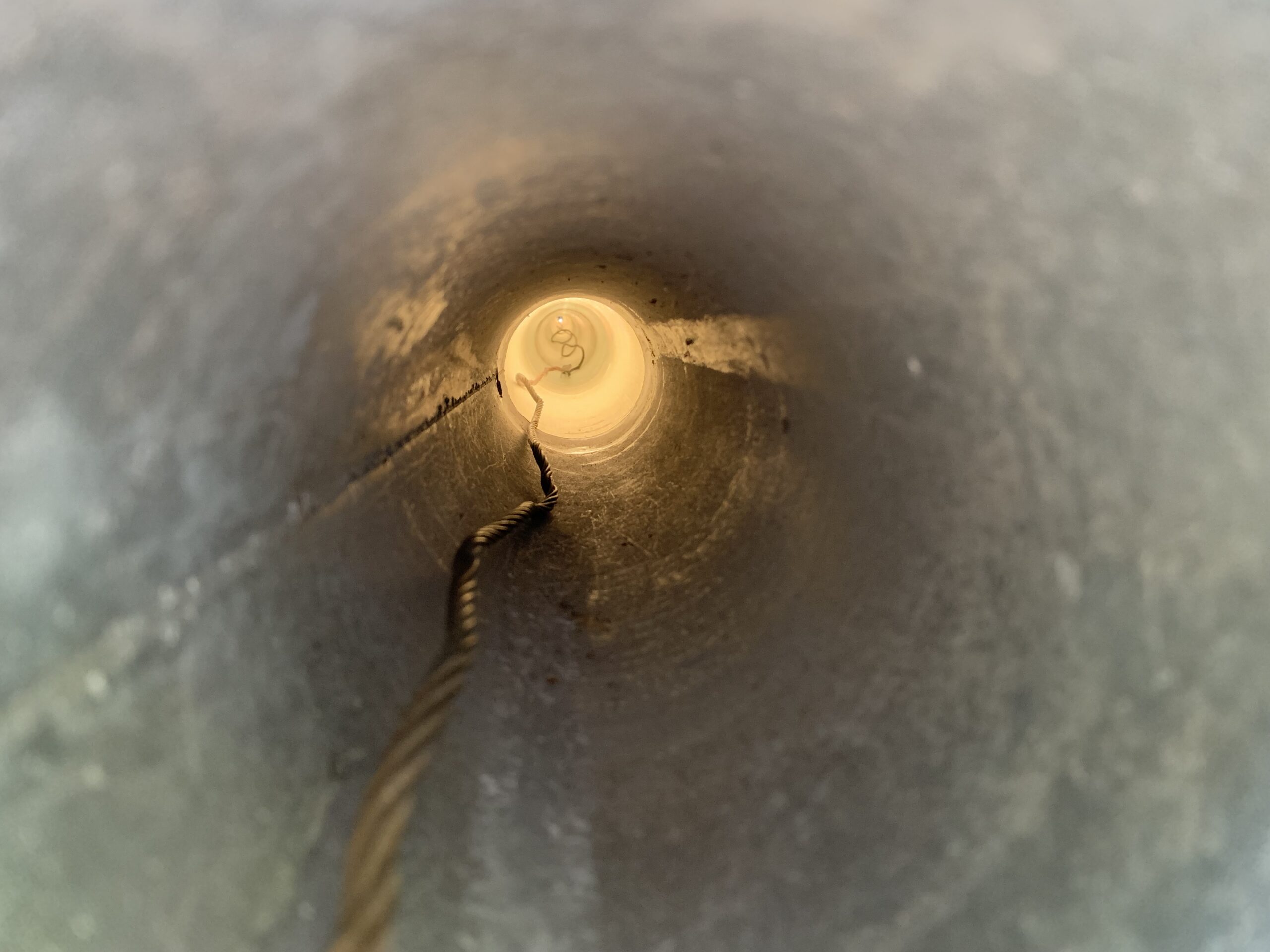
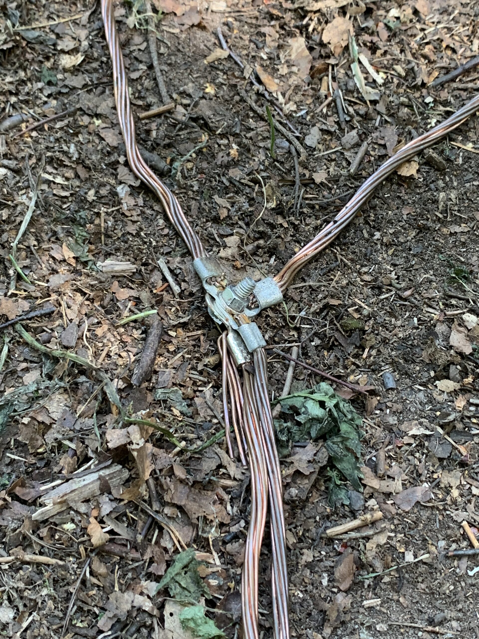
Power and network cable are installed inside a underground tubing, grounding copper wire is directly on the ground connecting all four poles of the cabin and also the antenna mast to the same common ground with all the antennas, radios and all other low voltage devices used in the cabin (lights, security cameras and so on).
All the playhouse electric outlets are 12V DC, for lights and toys and decoration, and installed so high that the smallest kiddies cannot reach them.
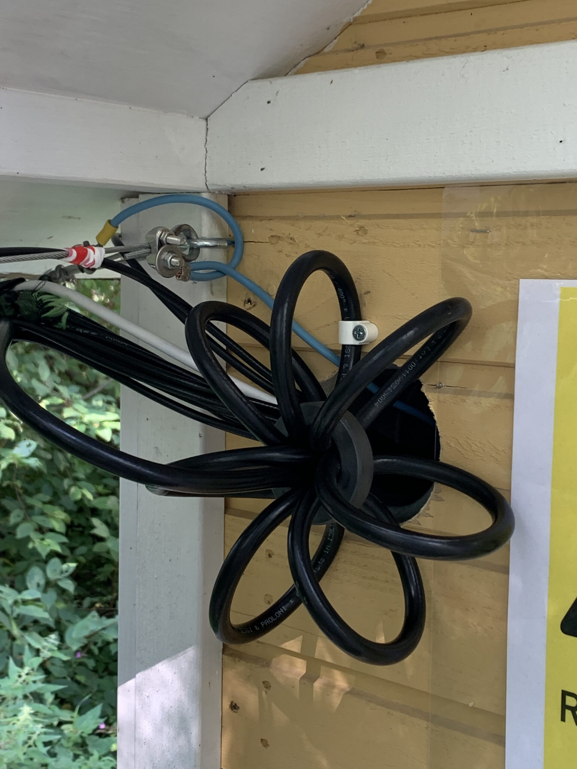
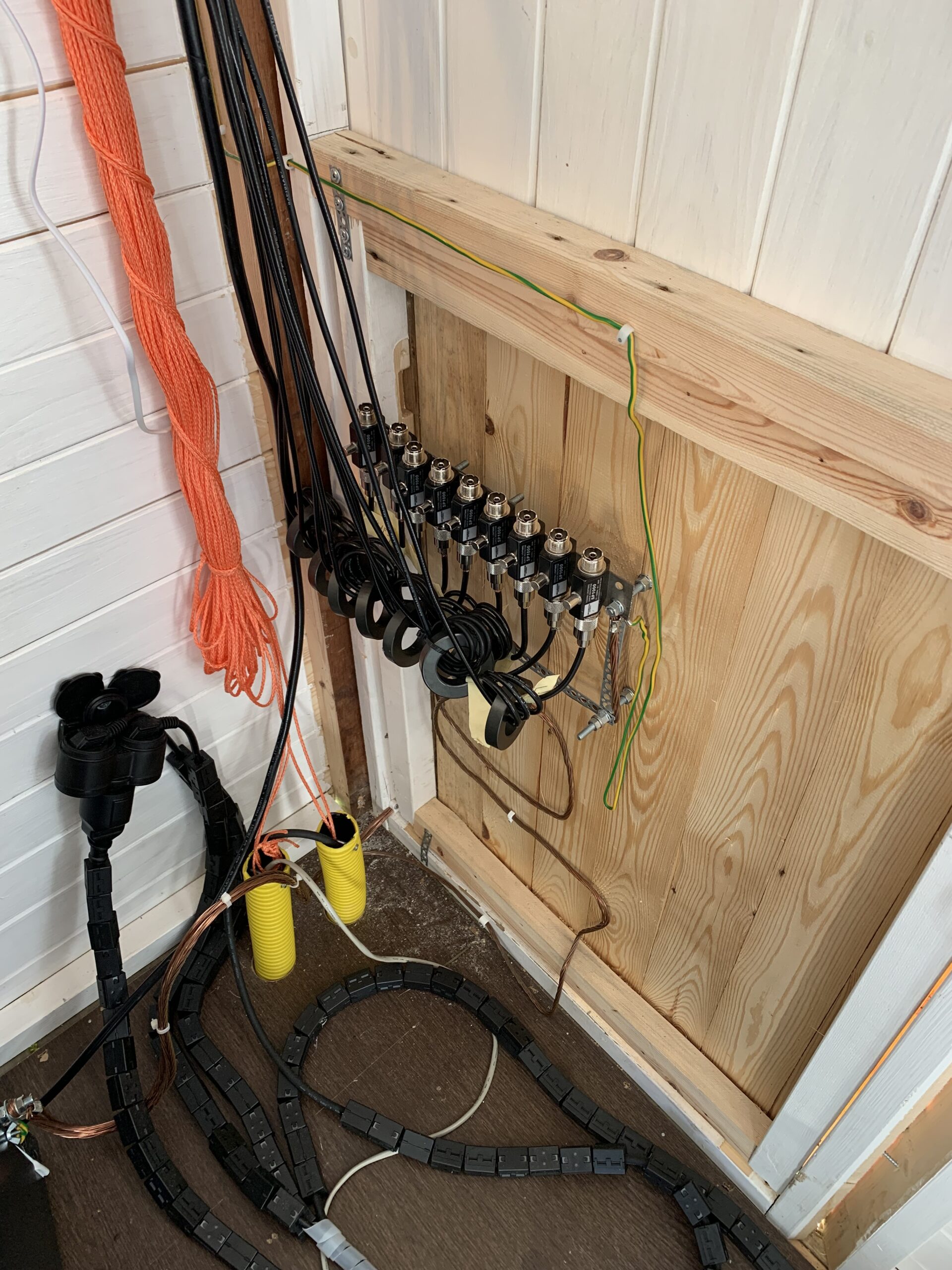
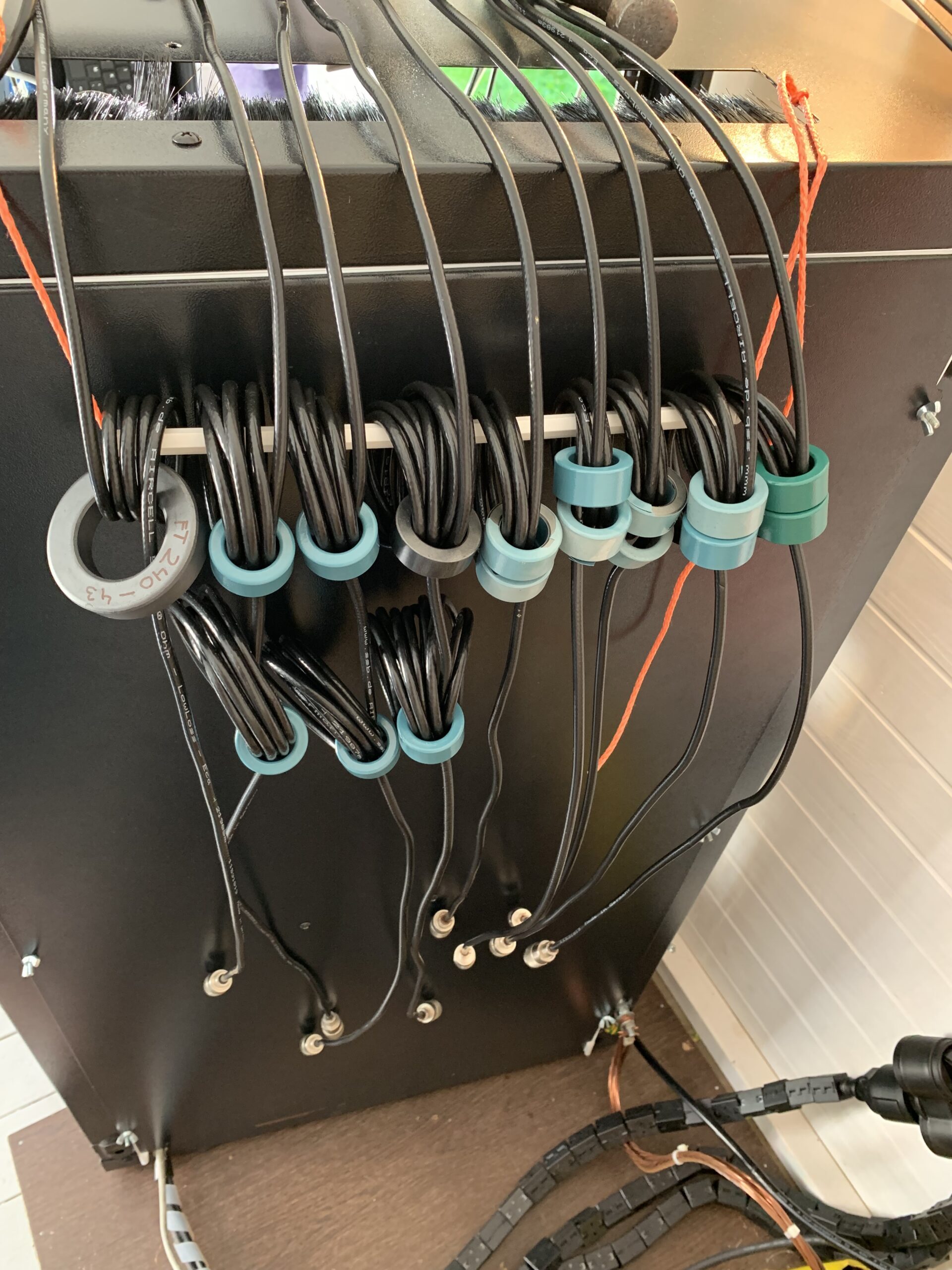
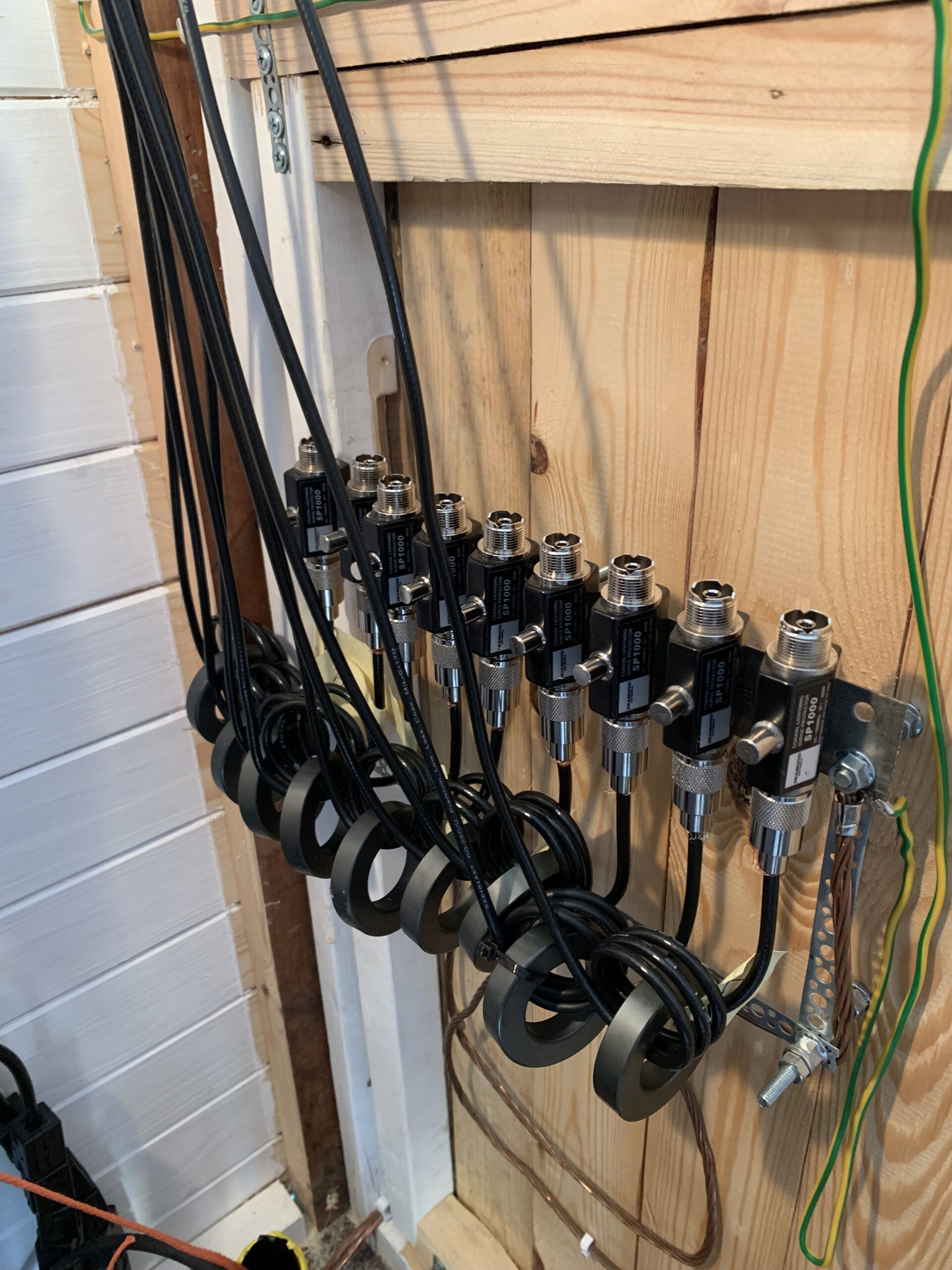
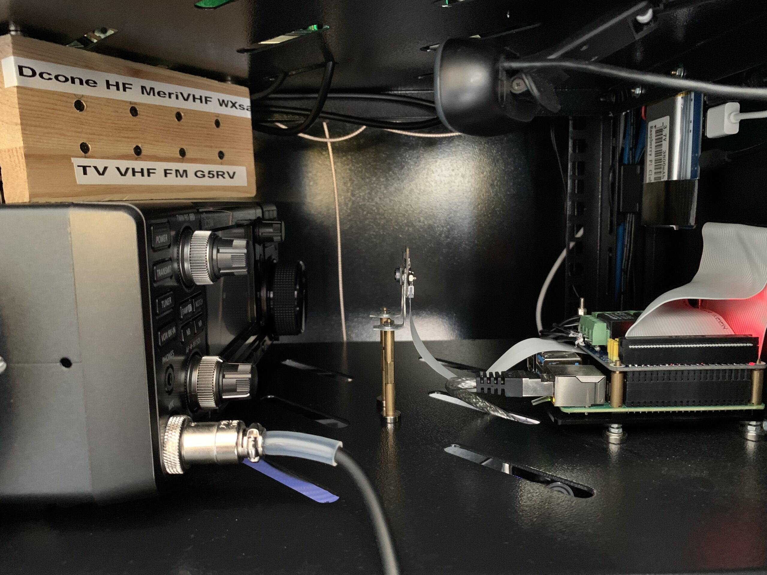
Third phase, antenna cabling. Currently there are fifteen different antennas connected to the system. Some of them requires lightning protection, some does not. Some are used for Ghz bands, some for VLF. All the antenna cables are protected at least with ferrite ring against RF interference, most of the antennas also with gas tube lightning protectors. Transmit antenna uses thick 10mm EcoFlex coaxial cable.
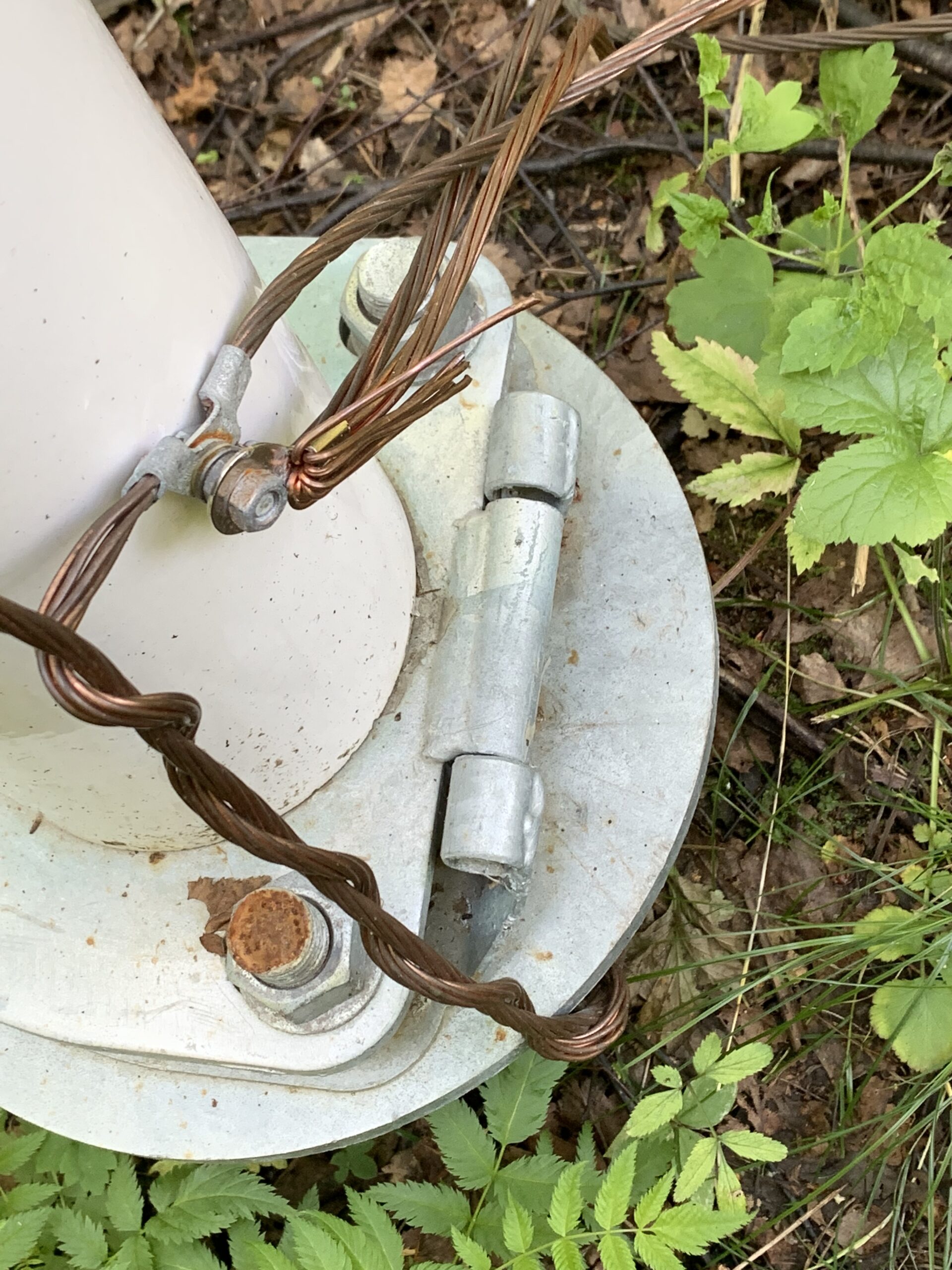
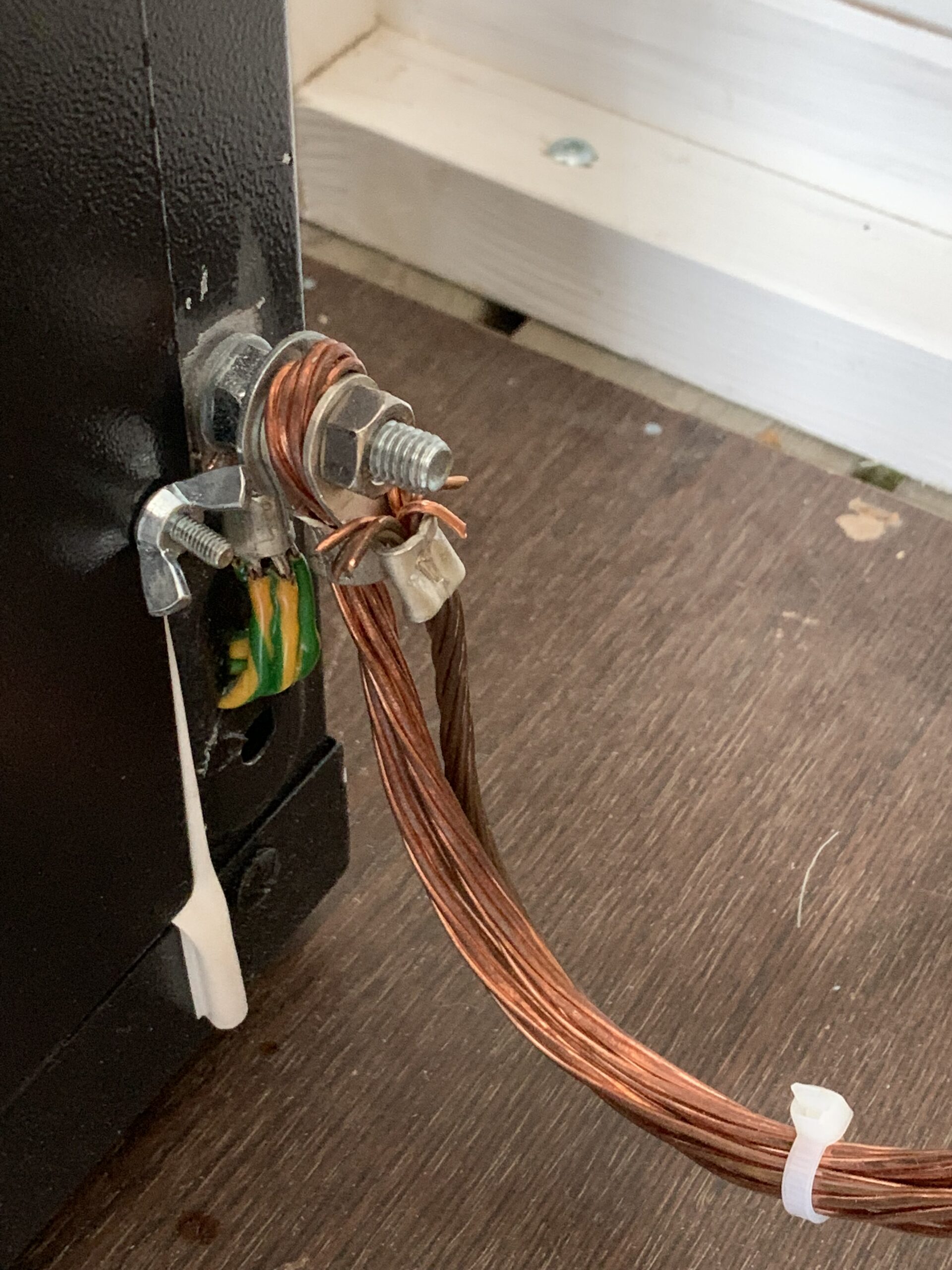
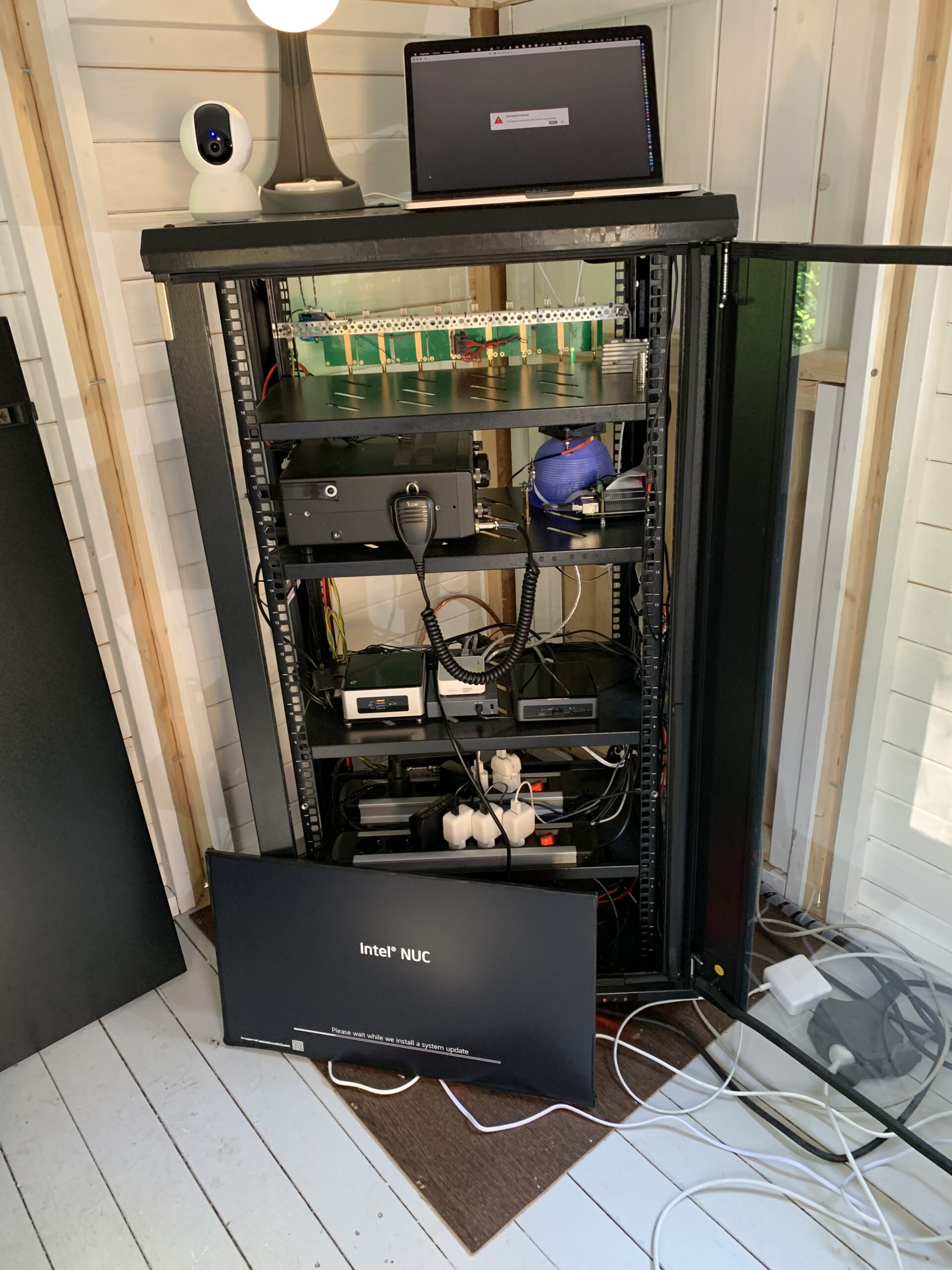
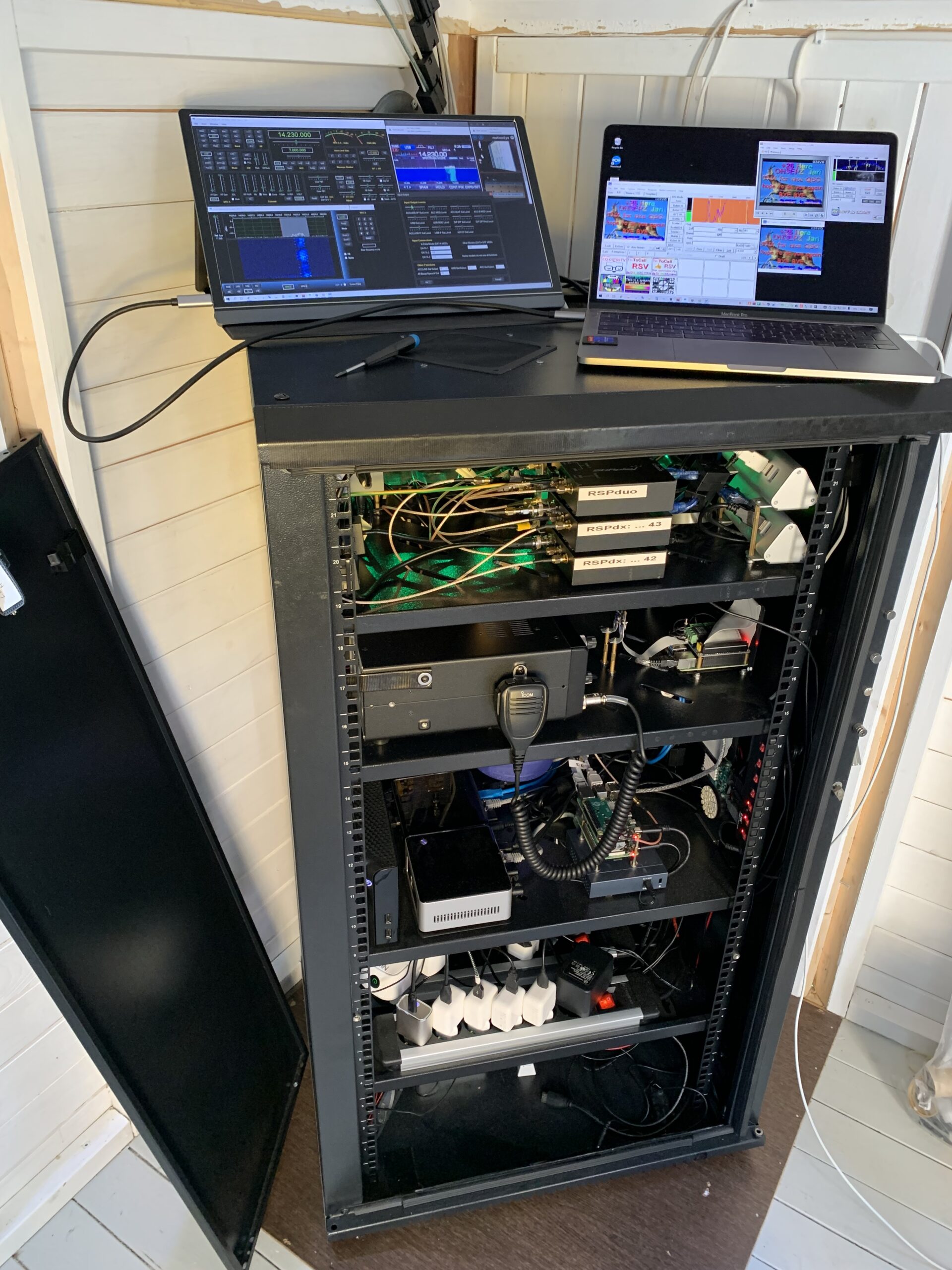
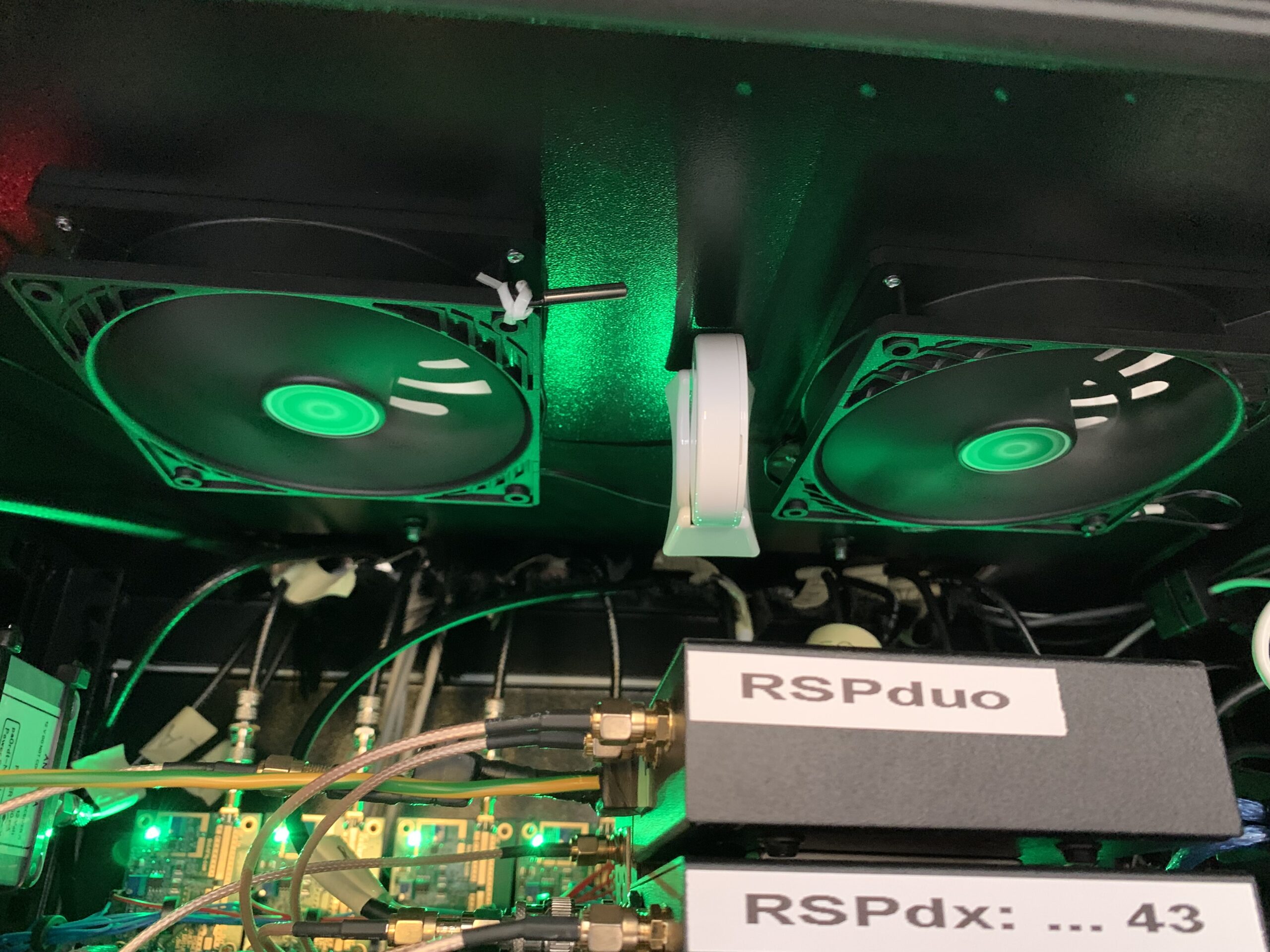
Fourth phase, The Radio-Cabin. All the radios (SDR’s) and transmitting rig (Icom IC-7300), PSU’s and computers are installed inside a standard metallic U-rack. The rack has been grounded to the same grounding with cabin poles, all the antennas and the antenna mast. There are also tens of meters of copper wire burried underground together with 5 meters of copper tubing in several locations around the premises. All this is to be sure that the grounding is perfect for both EMI & RF protection but also for lightning protections and preventation of the static electricity build up with the antennas.
Radio-cabin has also remote controlled security camera installed inside, mainly used for just maintenance and checking led’s and other lights computers have. Icom has it’s own high resolution camera pointing directly to it’s screen so that I can see a real time stream of the actual display of the Icom in case the remote controlling software has some problems to display data.
At the bottom of the Radio-cabin there is a cheap 15″ monitor screen. As there are lots of computers and sometimes one needs to see whats happening in the console I installed a screen at the bottom of the Radio-cabin. When not in console use it can play a HD “Fireplace” movie for the kids playing in the playhouse. It even has small speakers so one can hear the crackling noise of the fire. This is remotely controlled screen so it is not on 24/7 not only to save the life of the screen but also this kind of screen is a huge source of RF interference.
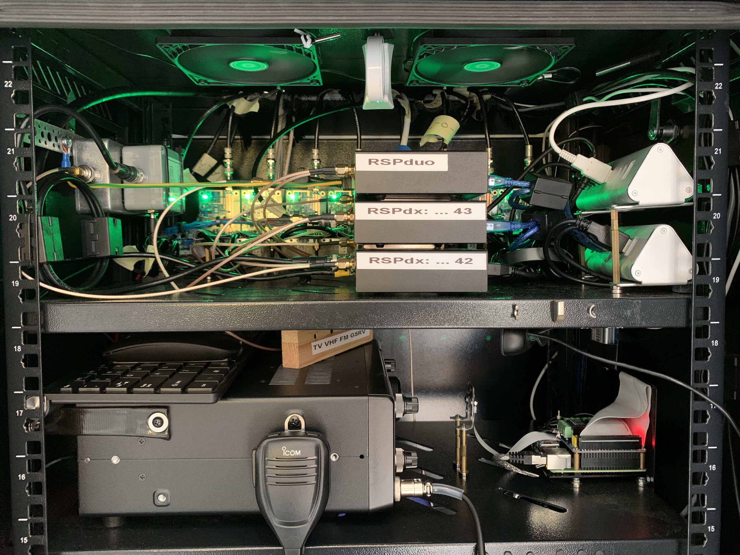
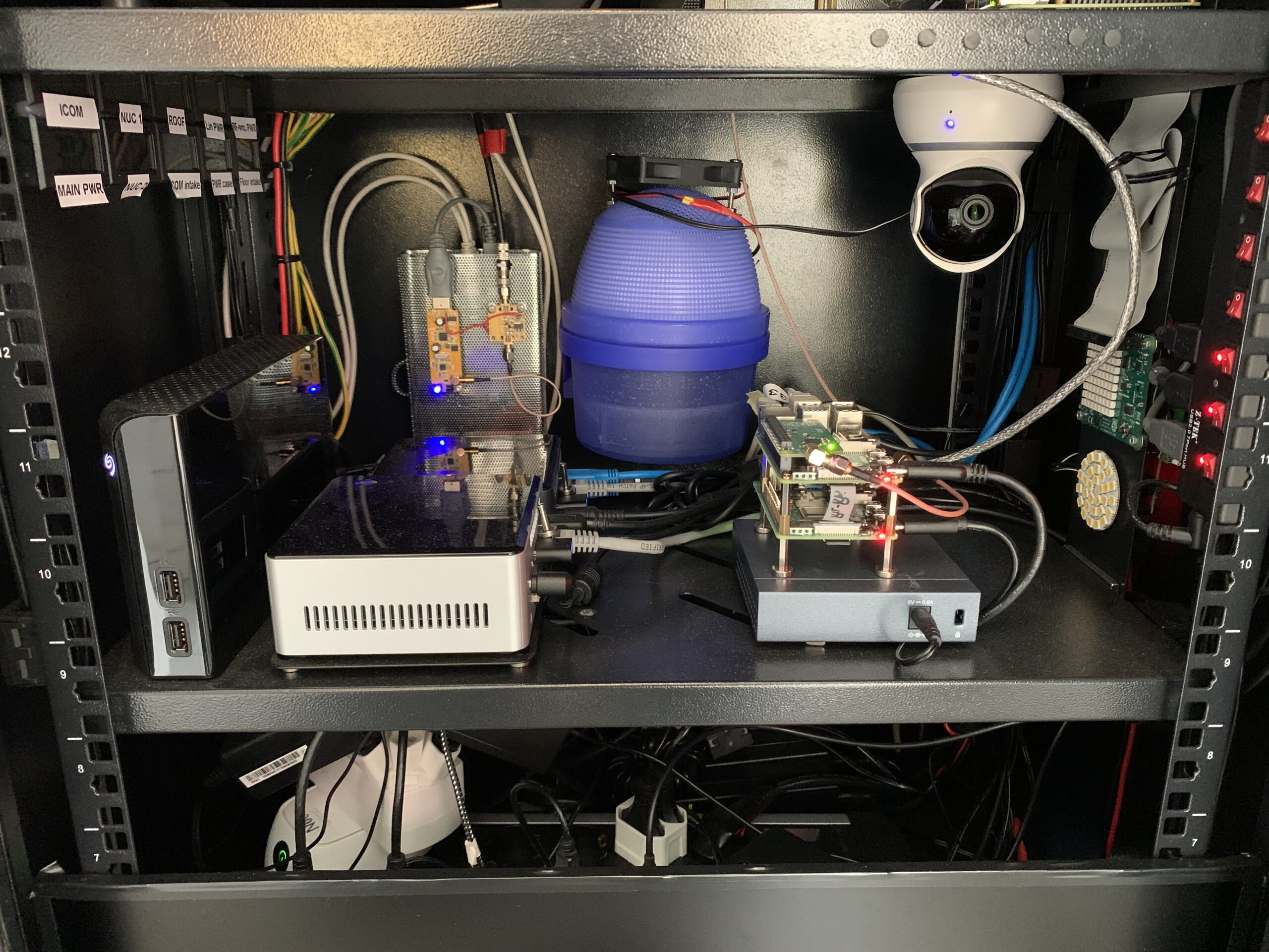
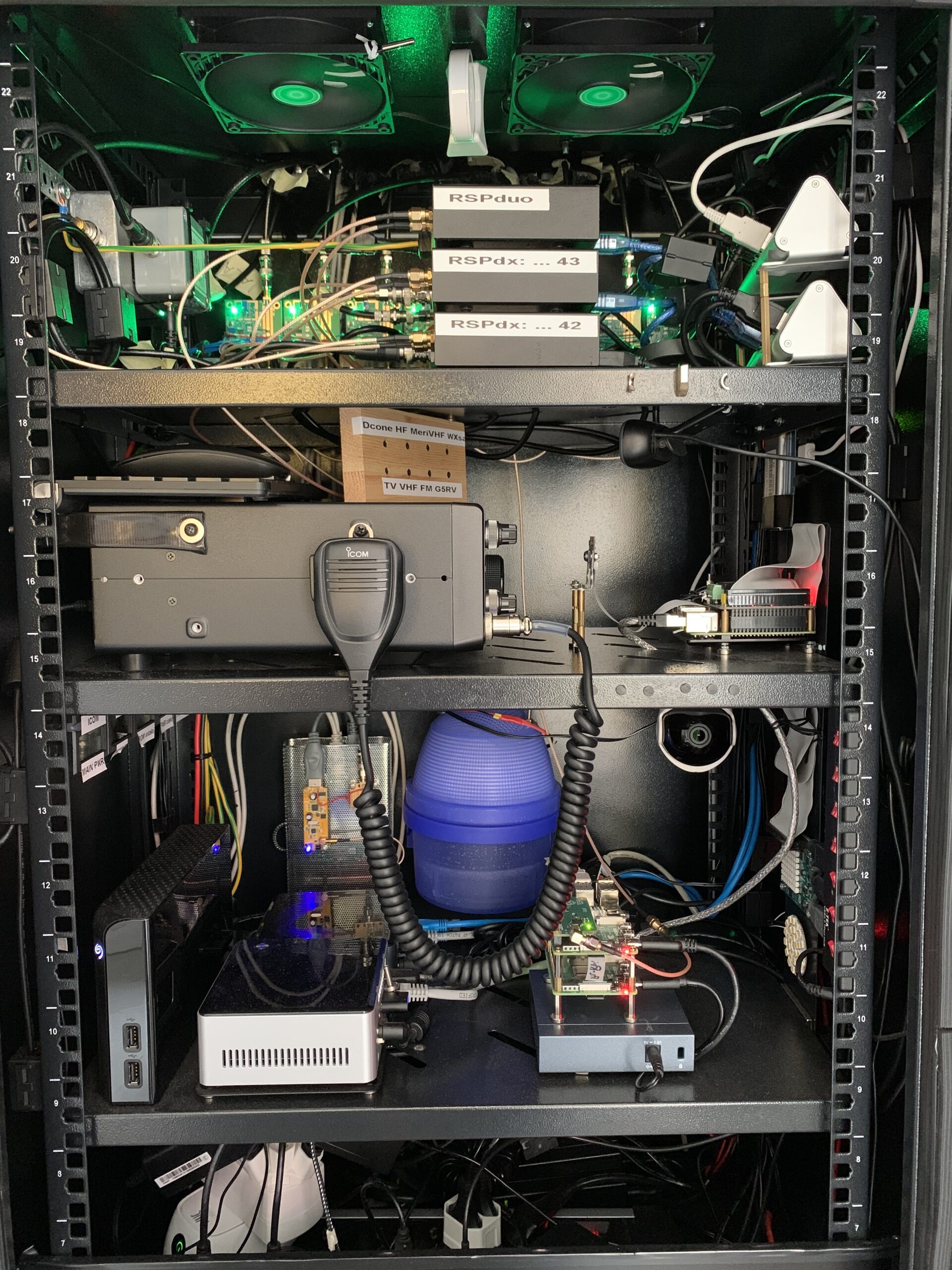
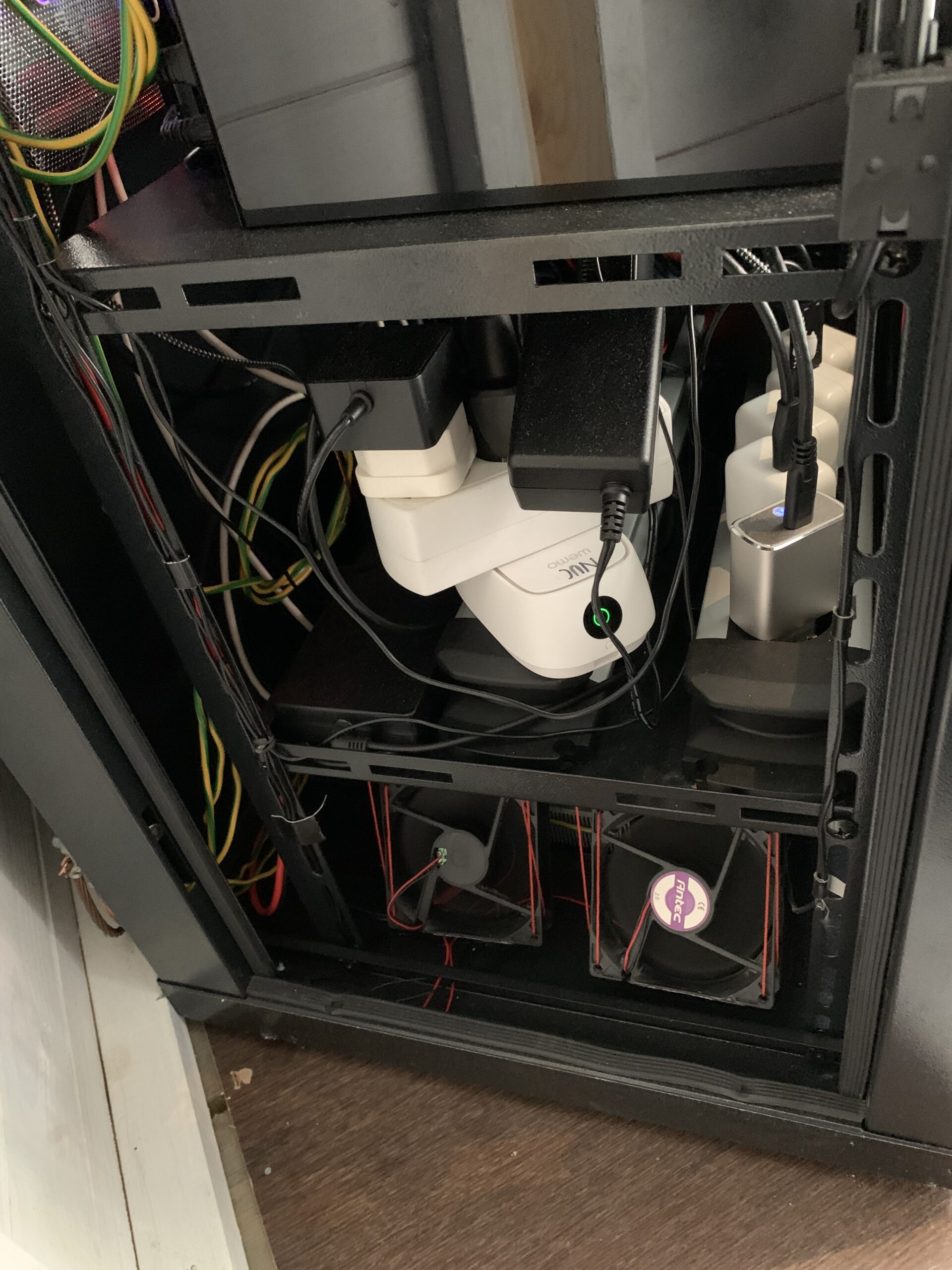
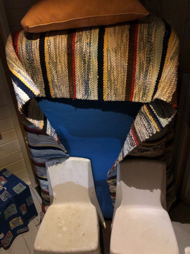
Temperature and humidity control. As there are several devices creating a lot of warm air I installed remote and thermostate controlled fans to the bottom of the Radio-cabin and also to the roof of it. Three Ruuvi-Tag sensors measure the temperature and humidity inside the Radio-cabin and in case of too warm, too cold or too humid values inside the cabin the fans are started. Floor fans circulate the air inside the Radio-cabin to level the temperature, if that is not enough the roof fans are started and will push hot air out from the Radio-cabin. Fresh cold air is sucked via floor vent (filtered). There is also humidity collector bucket (that blue one) that keeps the overal humidity in control. It uses a special chemical compound that ‘melts’ slowly from solid to liquid by absorbing humidity from the air. It has a small fan installed to the top of it to speed up the air circulation (can be remotely controlled on or off).
Based on my experiences, the Radio-cabin internal temperatule is above 0°C when the external temperature is not under -15°C. In case the external temperature is lower than -15°C a good external isolation is needed – so during winter time the Radio-cabin has it’s own “overals”. With this the internal temperature stays always over 0°C even when there is -25°C or more outside.
The system has worked without any problems with external temperatures of -28°C to +43°C.
Final step, The Security. As the playhouse has quite expencive equipment installed and only some plexiglass windows and thin wooden walls protecting them it was important to have some security installed. The cabin itself has several RuuviTag sensor measurin all the movement of the cabin. The sensors are so sensitive that if some one walks near the cabin the sensors can measure it. The tremors that opening the door of the playhouse or some one trying to open the Radio-cabin by force causes, triggers audible alarm played by one of the computers installed in to the Radio-cabin. Also a email alert is sent to my email address. There is also another security camera that records any movement with audio, so if some one tries to steal something he/she will be recorded with HD resolution and sound. Camera is also equipped with two way intercom, so I can speak to whome ever there is at that moment next to it. The camera and it’s internet connection are also battery powered so even if the main power is down there is power in these security features for several hours.
Final words
This has been extremely interesting and fun project. Not only with the SDR & HAM radio stuff, but to build such playhome, power systems, security and all the other things needed for such system. I am sure that as it happened with my SDR’s, this playhouse project continues to grow year after year – I’ll try to keep you posted about the latest modifications with it.
73’s! de OH1MAC a.k.a Mac